Ruggedizing Roving Edge Infrastructure Devices
Describes how to install the ruggedizing protections to your Roving Edge Infrastructure device.
Each Oracle Roving Edge Device comes assembled in the ruggedized case. Follow the instructions in this section to use your Roving Edge Device within its ruggedized case. Removing the device from the case is not recommended and might damage the device.
-
Remove the endcaps from the Ruggedized Transit Case by locating the wing-turn latches on both sides and turning these counter clockwise as shown to unlatch each endcap.
Wing-Turn Latch Location
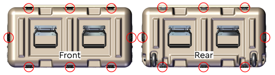
The wing-turn latches can be found in the locations shown. There are a total of eight wing-turn latches on each cap.
Wing-Turn Latch Operation
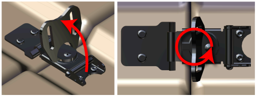
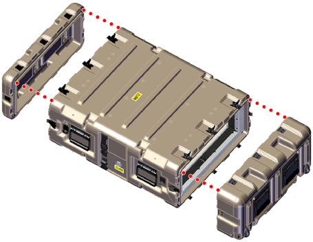
Pull the endcaps away from the case.
Removing the Endcaps from the Ruggedized Transit Case
-
Prepare the EMI Filter assemblies for system installation.
Note
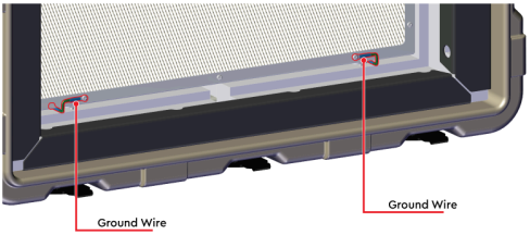
The EMI Filter assemblies will remain attached to the Faraday Cage with ground cables during the installation of the system. These ground cables are delicate and may be damaged if the EMI Filter assembly is pulled too hard.
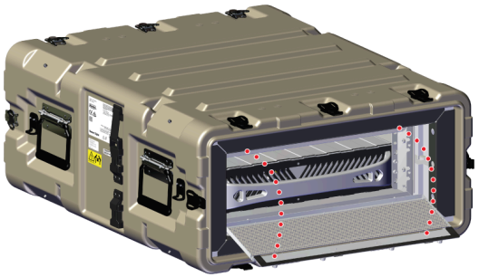
From the front of the Ruggedized Transit Case, use a T15 Torx.
Loosen the Front EMI Filter Assembly Captive Screws
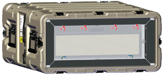
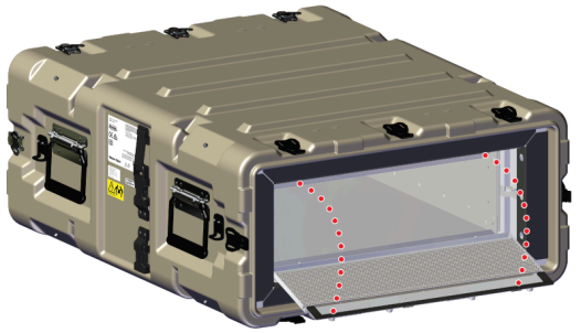
Carefully rotate the top of the EMI filter assembly down until it is resting on the case as shown in the following image.
Rotating the Front EMI Filter Assembly
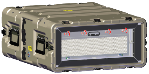
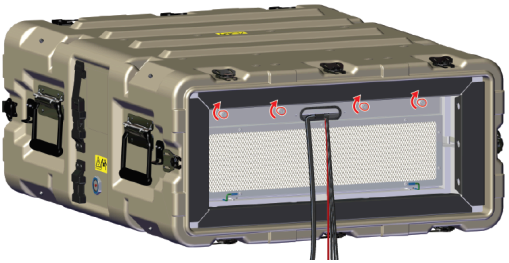
From the rear of the Ruggedized Transit Case, use a T15 Torx screwdriver to loosen the captive screws on the rear EMI Filter assembly.
Loosen the Rear EMI Filter Assembly Captive Screws
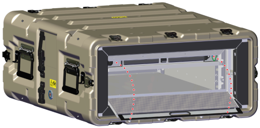
Carefully rotate the top of the EMI filter assembly down until it is resting on the case as shown in the following image. Be careful not to damage the ground wires attached to the bottom of the EMI filter assembly.
Rotating the Rear EMI Filter Assembly
-
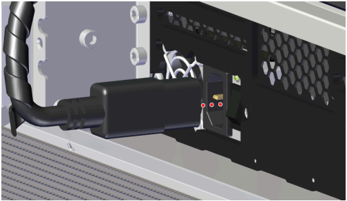
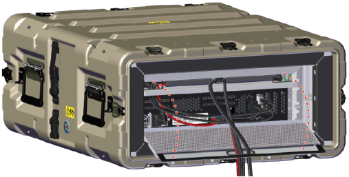
Connect the internal power cable from the Faraday cage to the rear of the system as shown:
Note
If the system and Ruggedized Transit Case configuration will be transported to another site, do not install the cables.
Connecting the Faraday Cage Power Cable
-
Install the data and power cables and re-seat the EMI Filter assembly onto the Faraday Cage.
Route the QSFP28, DB9, and Ethernet (optional) cables through the left cable channel and pull to ensure there is enough slack to connect the cables into each of their ports.
Data Cable Left Channel Route
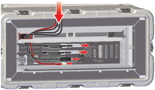
Connect each cable into the designated ports, route cable slack through the foam channels, and route the other end of the data cables through the oval cutout on the EMI Filter assembly.
Data Cable Left Channel Route
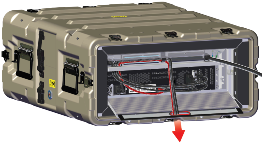
Connect the power cable into the port located in right cable channel, route cable slack through the foam channel and cable mount, and through the oval cutout on the EMI Filter assembly as shown.
Power Cable Connection and Routing
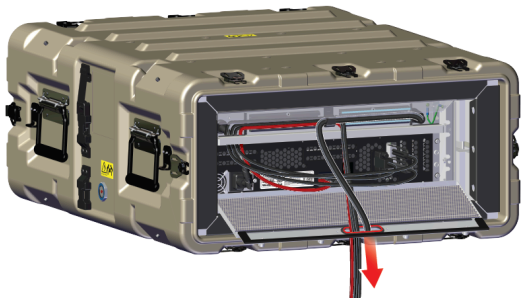
With the cables secured in place rotate and push the EMI Filter assembly forward to align the captive screws with the screw holes and begin tightening them with thumb and finger. Be sure to apply pressure as the foam channels that route cables will provide resistance. Once the cables and EMI filter are properly in place, use a T15 Torx screwdriver to tighten the captive screws on the front EMI Filter assembly.
Rotating and Seating the Rear EMI Filter Assembly
Tighten the Rear EMI Filter Assembly Captive Screws
-
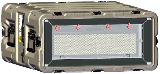
Identify the EMI Filter assembly for the front end of the Faraday cage. The front EMI Filter assembly will be a full screen, whereas the rear EMI Filter will have an oval cutout for routing cabling to the rear of the enclosure.
From the front of the Ruggedized Transit Case, carefully rotate the top of the EMI filter assembly up until it is aligned with the EMI filter assembly screw holes on the Faraday Cage as shown in the following image. Be careful not to damage the ground wires attached to the bottom of the EMI filter assembly.
Rotating and Seating the Front EMI Filter Assembly
Use a T15 Torx screwdriver to tighten the captive screws on the front EMI Filter assembly.
Securing the Front EMI Filter Assembly
Be aware and ensure that the ground cables on the EMI Filter assembly do not get pinched during re-installation.
Ground Wire Identification