Scenario: Receiving Commands and Sending Responses using MQTTs
Use this scenario to receive commands in the cloud and send responses to a device using the MQTTs protocol to interact with your Internet of Things (IoT) devices.
Tasks
To complete the steps below, you can use an existing IoT domain and IoT domain group or create an IoT domain group and an IoT domain and then complete the following steps.
Step 1: Create a Digital Twin Instance
Using the CLI
- When you create a digital twin instance use a secret or a certificate so the digital twin instance can securely authenticate. You must create a secret or create a certificate to complete this scenario. Oracle recommends using one secret for each digital twin instance and for production the digital twin instance should use a mTLS certificate for authentication.
Use the
oci iot digital-twin-instance createcommand and required parameters to create a digital twin. The following example shows the command how to use the authentication ID parameter with the required IoT domain parameter to associate the IoT domain to the digital twin instance:oci iot digital-twin-instance create --auth-id <vault-secret-or-client-certificate-id> --iot-domain-id <iot-domain-OCID>In this example response, notice the external key value. Use this external key value, notice the external key that's the device username that you can use in the next step:
"external-key": "<unique-id>"{ "data": { "auth-id": "<vault-secret-or-certificate-OCID>", "defined-tags": { "Oracle-Tags": { "CreatedBy": "default/user@oracle.com", "CreatedOn": "2025-08-05T18:03:15.264Z" } }, "description": null, "digital-twin-adapter-id": null, "digital-twin-model-id": null, "digital-twin-model-spec-uri": null, "display-name": "HVAC-instance", "external-key": "<unique-id>", "freeform-tags": {}, "id": "<iot-digital-twin-instance-OCID>", "iot-domain-id": "<iot-domain-OCID>", "lifecycle-state": "ACTIVE", "system-tags": {}, "time-created": "2025-08-05T18:03:15.870000+00:00", "time-updated": "2025-08-05T18:03:15.870000+00:00" }, "etag": "<unique-id>" }
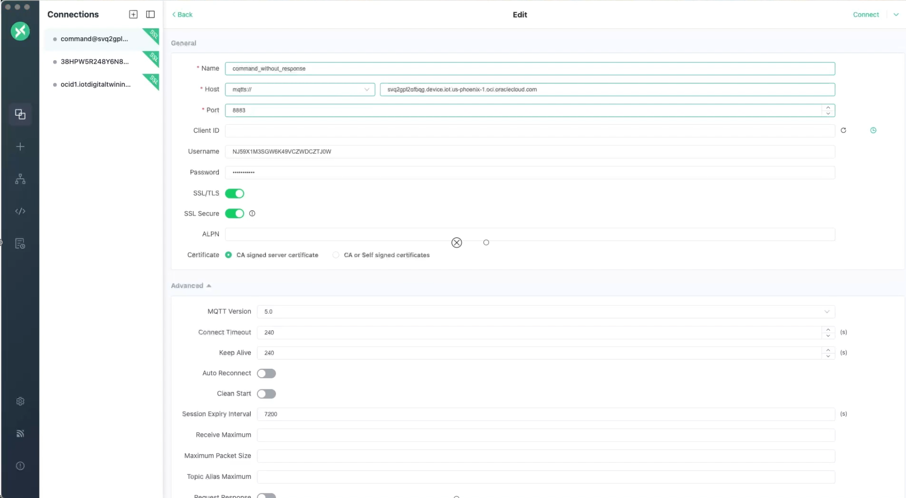
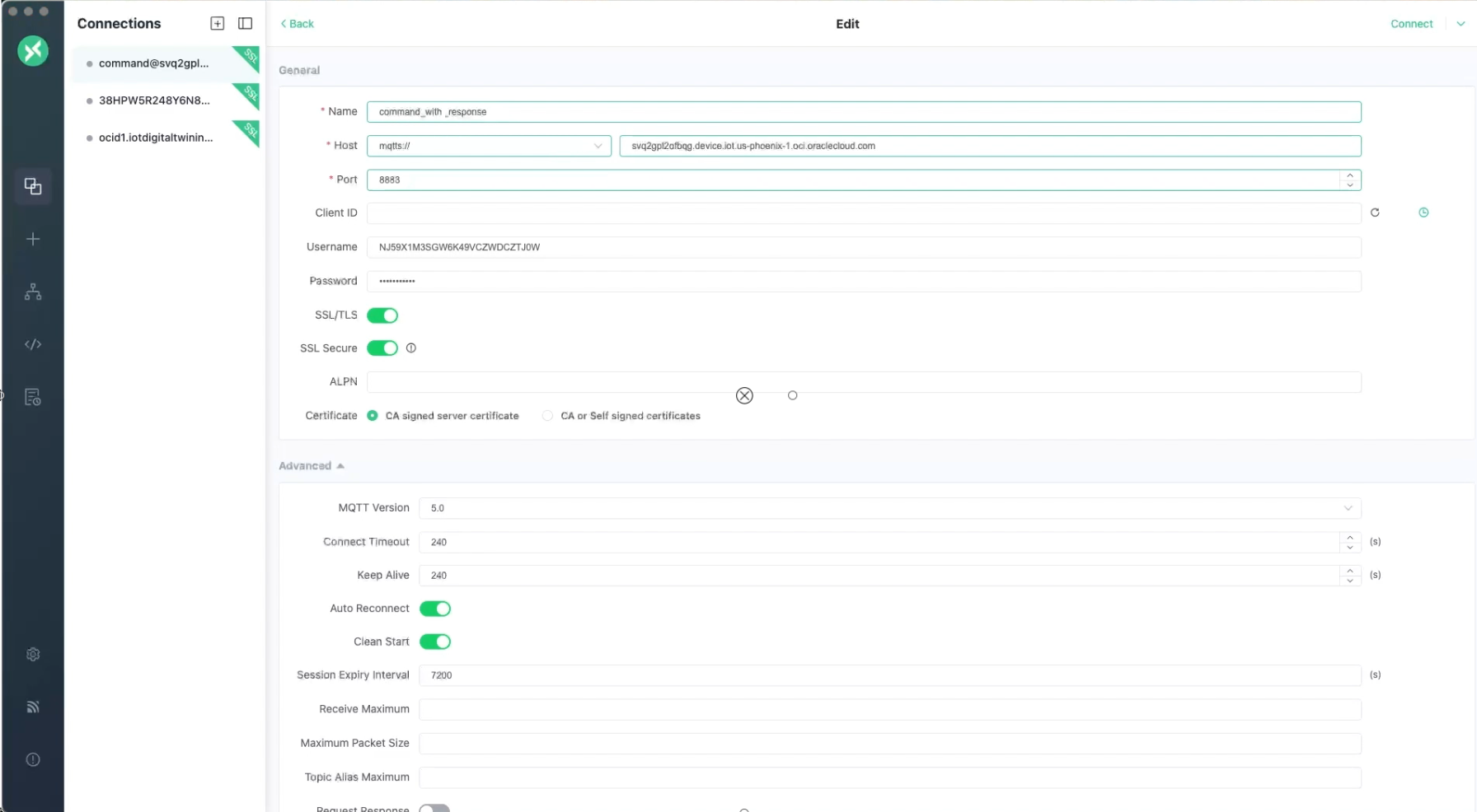
Step 2: Establish the MQTT session using broker credentials
- Download and set up MQTTX follow these instructions, see Getting Started with MQTTX. Open MQTTX.
- Select + New Connection, to create a new connection. Enter a name for the connection, avoid entering confidential information.
- Enter the external key
<unique-id>value as the Username. You can find the external key in theoci iot digital-twin-instance createresponse, from the previous Step 1: Create a Digital Twin Instance:"external-key": "<unique-id>" - Enter the device password. If you use vault secret this must be the plain text secret, or you can use an mTLS certificate.
- Enter the Host. Select the
mqtts://protocol from the host drop-down list and enter the device host:<domain-short-id>.device.iot.<region>.oci.oraclecloud.comfrom the IoT domain, see Getting an IoT Domain's Details. - Enter the port, for example:
8883Note
Currently, MQTT Secure (MQTTS) is only supported using port8883. - Turn on the toggle SSL/TLS.
- Turn on the toggle SSL Secure.
- For the Certificate, select the CA signed server certificate option.
- When you configure the MQTTX connection make sure to connect using:
clean session: Set the clean session option totrue. When clean session is set to true, the broker doesn’t retain any information for the client and discards any previous state from any persistent session. All session data is deleted as soon as the network connection is closed.- Set the
Last-Will-Retainoption tofalseto allow client subscriptions to be retained if the device briefly disconnects.
- Set the Last Will QoS to 1. To define the reliability of the "At Least Once" delivery for your disconnect notification.
- Select Connect.
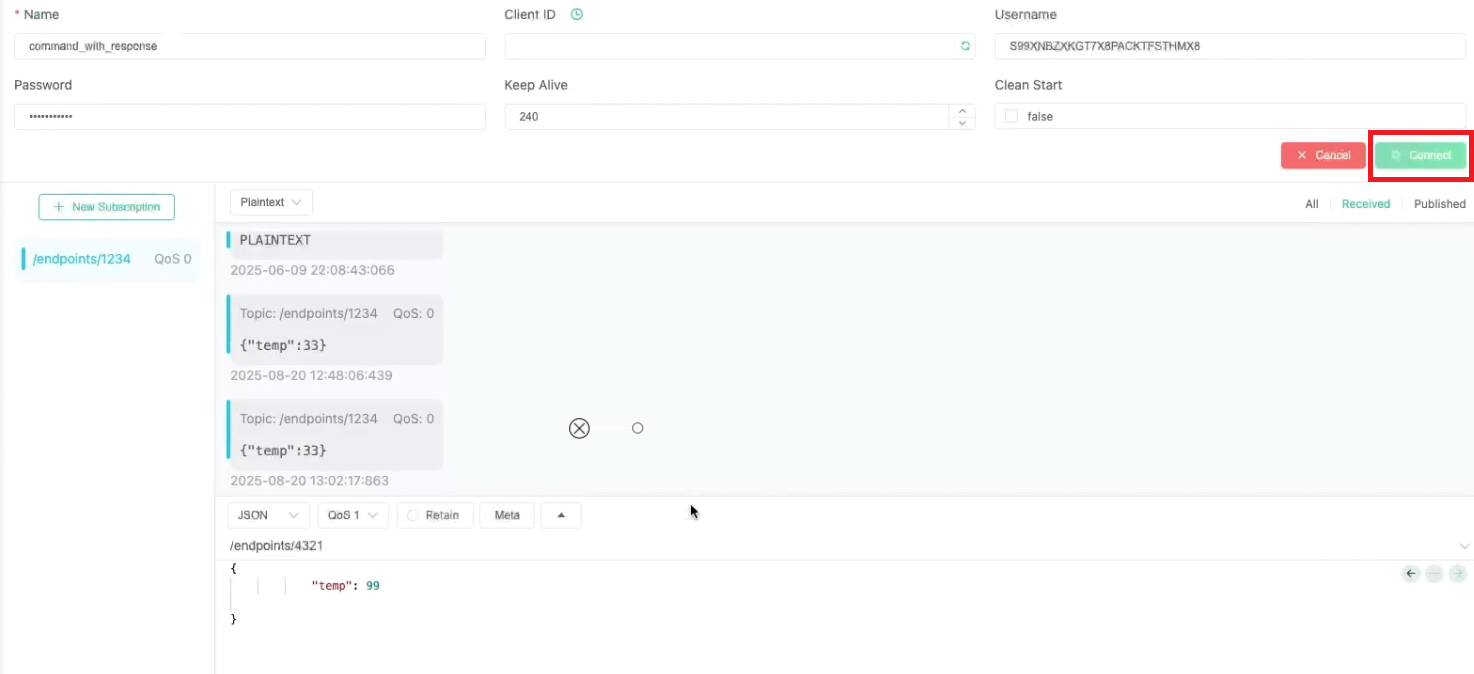
This image shows these settings in MQTTX, right click and open in a new tab to view a larger screenshot.
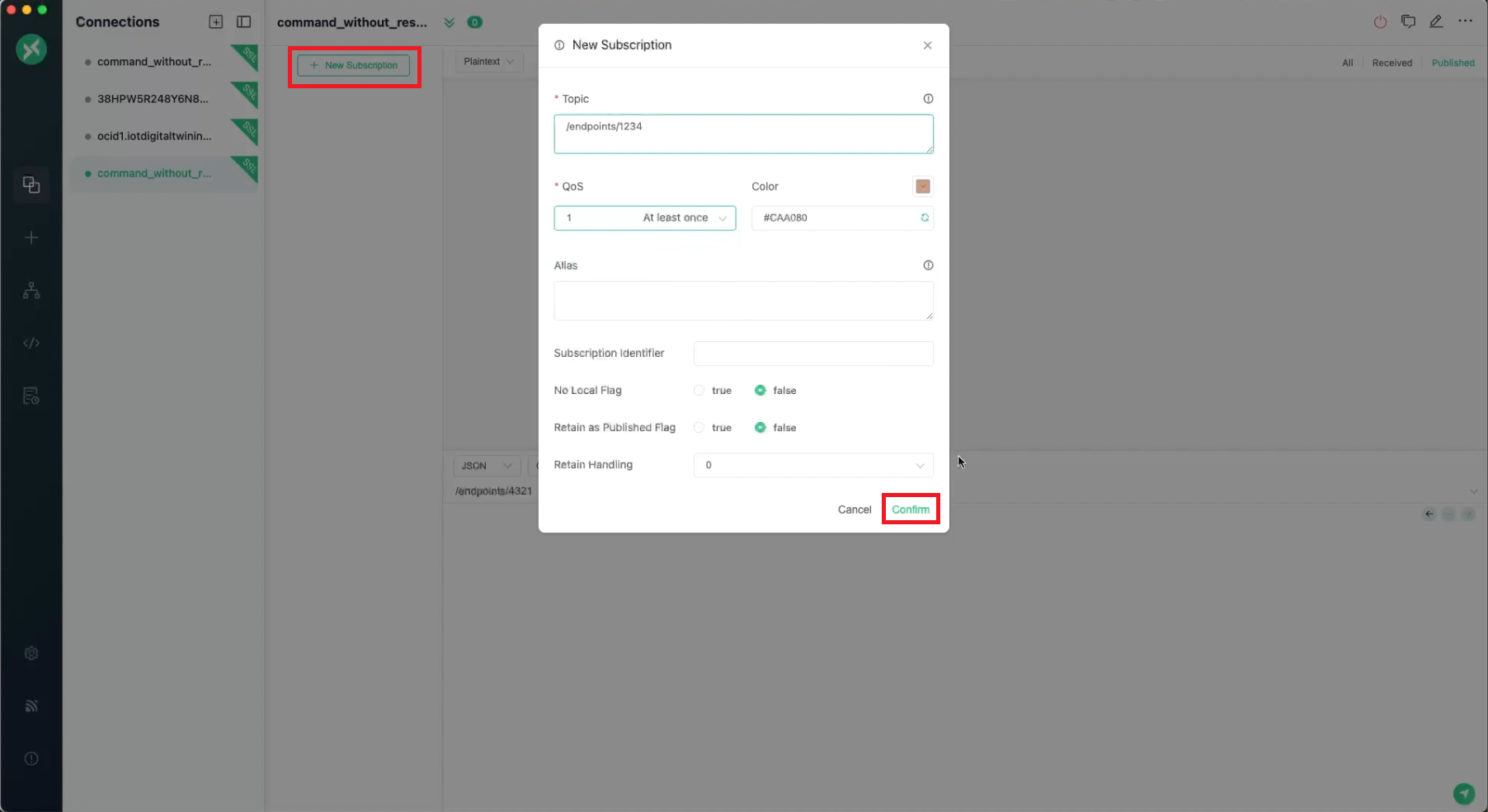
Step 3: Subscribe to a Topic to Receive Responses in MQTTX
When an external system or IoT device publishes a message to the subscribed topic, in MQTTX you view the incoming messages under that topic. If you are awaiting a response from a prior command, ensure you are subscribed to the correct response topic.
Define the responseEndpoint in the next step when you define the command in a JSON file. The "responseEndpoint": "/endpoints/4321" string represents the topic or endpoint path where the device should publish its response. Choose any logical endpoint path for your digital twin routes. You must use the same path on both the cloud side (when sending the command) and the device side (when publishing the response).
- In MQTTX, select + New Subscription.
- Enter the endpoint as the Topic.
- From QoS drop-down menu, select 1 At least once.
- Select Confirm.
- Client ID: your-client-id
- Username: External ID.
- Password: Enter the device password.
- Enter
mqtts://with the IoT domain's device host and using port number 8883:mqtts://<iot-domain-short-id>.device.iot.<region>.oci.oraclecloud.com:8883
.
Step 4: Define the Command in a JSON file
You can define the command details in a JSON file and use this file in the next step to Invoke a Raw JSON Command on a Device.
For this example, save this snippet to a command.json file so that you can use it to invoke the command and process the response according to instructions in the file.
{
  "requestEndpoint": "/endpoints/1234",
  "requestDuration": "PT3M",
  "requestDataFormat": "JSON",
  "requestData": {
    "temp": 33
  },
  "requestDataContentType": "application/json",
  "responseEndpoint": "/endpoints/4321",
  "responseDuration": "PT3M"
}requestEndpoint: The URL path/endpoints/1234where the request will be sent. This is typically an API endpoint or an address where the IoT Platform listens for commands.If you already have an endpoint dedicated to responses for example:
/endpoints/<external-id>/responseuse that path inresponseEndpoint.Or create a new
endpoint/routefor the digital twin instance in the digital twin adapter's inbound routing rules that the device can publish to. Reference that path in thecommand.jsonfile. Keep the endpoint path consistent, whatever path you define inresponseEndpointbecomes the MQTT topic that your client must subscribe to in Step 3 so you can see the command's response.requestDuration: The allowed or requested duration for the request to complete, in ISO 8601 duration format. For example,PT3Mequals 3 minutes.requestDataFormat: Specifies the date format for the data sent in the JSON request.requestData: The JSON payload that's sent with a key value pair to set a temperature value on the device:"temp": 33
Step 5: Invoke a Raw JSON Command on a Device
You can use the CLI or the API to invoke a command on a device, the following example uses the CLI.
Using the CLI
Use the oci iot digital-twin-instance invoke-raw-json-command command and parameters to invoke a raw JSON command on a device.
- Replace the <digital-twin-instance-OCID> with the digital twin instance OCID from Step 1: Create a Digital Twin Instance.
- Use the
command.jsonfile from the previous Step 2: Define the Command in a JSON file. - Replace
/endpoints/1234with the value you defined in thecommand.jsonfile for the--request-endpointparameter.
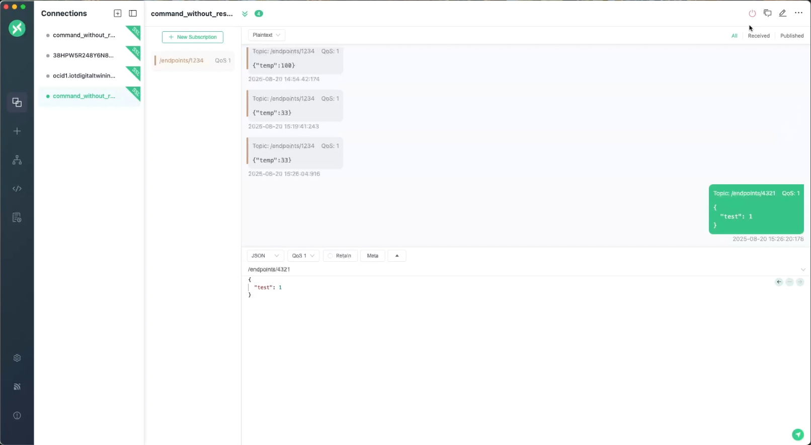
oci iot digital-twin-instance invoke-raw-json-command --digital-twin-instance-id <digital-twin-instance-OCID> --request-endpoint "/endpoints/1234" --from-json file://command.jsonStep 6: Verify in MQTTX
{
    "temp": 33
  }
To view a larger screenshot, right click and open in a new tab.
| Scenario | Device State | Expected Command State | Comments |
|---|---|---|---|
| Not Connected | Not connected not subscribed | REFUSED | Command delivery fails immediately |
| Connected but not subscribed | Connected | REFUSED | Device online but does not receive command |
| Subscribed but not connected | Subscribed only | PENDING → EXPIRED | Command waits; expires after timeout |
| Subscribed but not connected initially and gets connected before timeout | Initially offline | PENDING → SENT | Command Received |
| Connected and subscribed | Connected and Subscribed | SENT | Command Received |
| One-Way Command (No response expected) | Connected and Subscribed | COMPLETED | Response is not expected and tracked |
| Two-Way Command (No response received) | Connected and Subscribed | NOT_RESPONDED | Device does not respond within response duration timeout |
| Two-Way Command (response received) | Connected and Subscribed | COMPLETED | Device sends data within response time out and complete the flow |
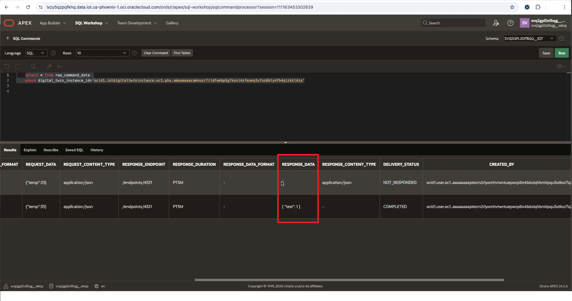
Step 7: Monitor the Command's Delivery Status in APEX
To view your IoT data in APEX requires configuring access to your data. After that configuration is complete, you can use APEX to work with your IoT data.
- In APEX, log in to the specific IoT domain's Workspace using the following as the workspace name and database user name. Notice the two underscores in the database schema name:Go to SQL Workshop and select SQL Commands to query the IoT data.
<domain-short-id-from-device-host>__IOT - Enter the following command, replace
<digital-twin-instance-OCID>with the digital twin OCID and select Run to query the raw command data:select * from raw_command_data where digital_twin_instance_id='<digital-twin-instance-OCID>' - In the Results, view the RESPONSE_DATA:
{"test":1}