Reference Topologies
These detailed topologies are examples of uplink configurations that have been tested and are known to work as expected. Each example includes a diagram for illustration, and configuration guidelines.
When preparing for the installation of Oracle Compute Cloud@Customer, you decide how the system will be connected to the data center network: uplink count, cabling pattern, connection speed, routing design, and so on. Decisions about uplinks are based on the network infrastructure in your data center, and the bandwidth and availability requirements of your Compute Cloud@Customer environment. These reference topologies help you make informed decisions for your specific environment, and provide guidance to configure your switches for the topology you select.
The configuration parameters provided in the reference topologies are intended as guidelines for network administrators. The exact configuration details of your specific environment must be aligned with your data center network design.
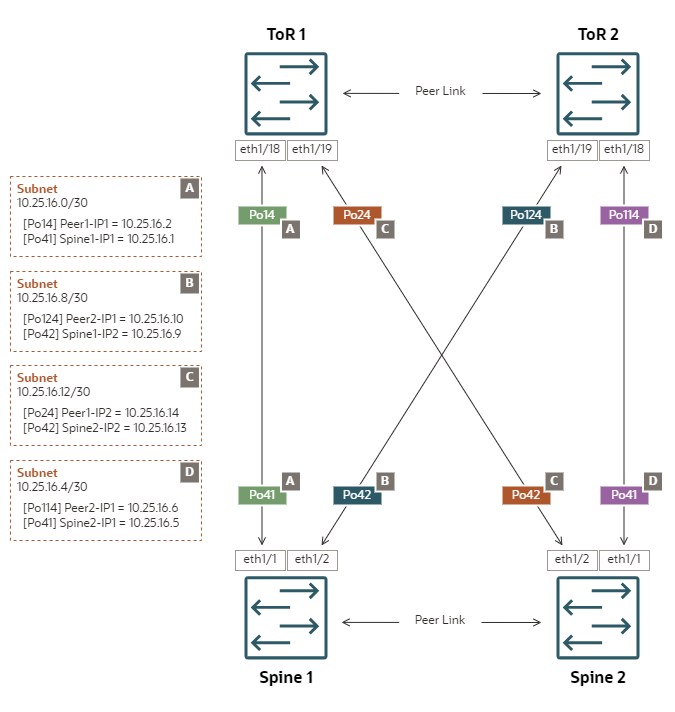
ECMP Mesh enables Layer 3 network deployment according to industry-proven best practices. This uplink topology is highly recommended.
Configuration Properties
-
Mesh topology – each spine switch is connected to two independent data center switches
-
Static routing – all egress traffic from an uplink goes through a single gateway IP configured on its peer network device in the data center
-
ECMP – bandwidth optimization across multiple redundant links or paths
-
Separate /30 subnets – each uplink connects one spine switch port channel to one data center switch port channel in a /30 subnet
Topology Highlights
-
All uplinks are configured as LACP/active port channels with rate=fast
-
Port channel Po41 represents the first set of links on both spine switches. They connect straight to the corresponding ToR switches.
-
Port channel Po42 represents the second set of links on both spine switches. They cross-connect to the corresponding ToR switches.
-
-
ToR switch ports connecting to the spine switches must be set up in access mode. Spanning tree protocol must be disabled.
-
Requires 4 unique subnets: a /30 subnet size is recommended, but /31 is possible if the ToR switches support it.
-
Equal cost static routes to both ToR switches are set up automatically.
-
Egress traffic can hash to any of the 4 uplinks.
-
It is NOT possible to isolate specific VCN/VM egress traffic through one particular uplink.
-

Detailed Spine Switch Configuration Example
-
Spine Switch 1
interface port-channel41
  description "customer uplink"
  no switchport
  mtu 9216
  speed 10000
  no negotiate auto
  ip access-group ingress-ports-acl in
  no ip redirects
  ip address 10.25.16.1/30
  ip nat outside

interface port-channel42
  description "customer uplink 2"
  no switchport
  mtu 9216
  speed 10000
  no negotiate auto
  ip access-group ingress-ports-acl in
  no ip redirects
  ip address 10.25.16.9/30
  ip nat outside

ip route 0.0.0.0/0 po41 10.25.16.2 20
ip route 0.0.0.0/0 po42 10.25.16.10 20
Routes added:
0.0.0.0/0, ubest/mbest: 2/0 *via 10.25.16.2, [20/0], 6d08h, static *via 10.25.16.10, [20/0], 6d08h, static -
Spine Switch 2
interface port-channel41
  description "customer uplink"
  no switchport
  mtu 9216
  speed 10000
  no negotiate auto
  ip access-group ingress-ports-acl in
  no ip redirects
  ip address 10.25.16.5/30
  ip nat outside

interface port-channel42
  description "customer uplink 2"
  no switchport
  mtu 9216
  speed 10000
  no negotiate auto
  ip access-group ingress-ports-acl in
  no ip redirects
  ip address 10.25.16.13/30
  ip nat outside

ip route 0.0.0.0/0 po41 10.25.16.6 20
ip route 0.0.0.0/0 po42 10.25.16.14 20
Routes added:
0.0.0.0/0, ubest/mbest: 2/0
  *via 10.25.16.6, [20/0], 6d07h, static
  *via 10.25.16.14, [20/0], 6d07h, static
VRRP Mesh would have a negative impact on network performance. This uplink topology is NOT recommended.
When the uplinks are set up in a mesh topology, there are 4 distinct Layer 3 uplinks to the ToR switches. In a Virtual Router Redundancy Protocol switch configuration, egress traffic is typically routed through the uplink with the primary/active role. Thus, a VRRP mesh configuration would reduce the egress bandwidth to only 25 percent of the actual capacity. Therefore, this configuration is considered not supported.
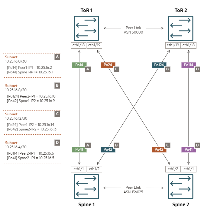
Dynamic Mesh enables Layer 3 network deployment according to industry-proven best practices. This uplink topology is highly recommended.
Configuration Properties
-
Mesh topology – each spine switch is connected to two independent data center switches
-
Dynamic routing – both peered Autonomous Systems, the appliance and the data center, exchange routing information using eBGP (external Border Gateway Protocol). The best routing path is dynamically adjusted based on network availability information advertized by each AS.
-
Separate /30 subnets – each uplink connects one spine switch port channel to one data center switch port channel in a /30 subnet
Topology Highlights
-
All uplinks are configured as LACP/active port channels with rate=fast
-
Port channel Po41 represents the first set of links on both spine switches. They connect straight to the corresponding ToR switches.
-
Port channel Po42 represents the second set of links on both spine switches. They cross-connect to the corresponding ToR switches.
-
-
ToR switch ports connecting to the spine switches must be set up in access mode. Spanning tree protocol must be disabled.
-
Requires 4 unique subnets: a /30 subnet size is recommended, but /31 is possible if the ToR switches support it.
-
Two eBGP peering sessions are established between each spine and both ToR switches.
-
Egress traffic can hash to any of the 4 uplinks.
-
It is NOT possible to isolate specific VCN/VM egress traffic through one particular uplink.
-

Spine Switch Configuration Details
-
Spine Switch 1
interface port-channel41 description "customer uplink" no switchport mtu 9216 speed 10000 no negotiate auto ip access-group ingress-ports-acl in no ip redirects ip address 10.25.16.1/30 ip nat outside interface port-channel42 description "customer uplink 2" no switchport mtu 9216 speed 10000 no negotiate auto ip access-group ingress-ports-acl in no ip redirects ip address 10.25.16.9/30 ip nat outside router bgp 136025 router-id 10.25.16.1 neighbor 10.25.16.2 bfd singlehop remote-as 50000 address-family ipv4 unicast neighbor 10.25.16.10 bfd singlehop remote-as 50000 address-family ipv4 unicast BGP Sessions: ASN 136025 VRF default, local ASN 136025 Neighbor ASN Flaps LastUpDn|LastRead|LastWrit St Port(L/R) Notif(S/R) 10.25.16.2 50000 0 1w4d |00:00:50|00:00:20 E 34408/179 0/0 10.25.16.10 50000 0 1w4d |00:00:43|00:00:20 E 57322/179 0/0 -
Spine Switch 2
interface port-channel41
  description "customer uplink"
  no switchport
  mtu 9216
  speed 10000
  no negotiate auto
  ip access-group ingress-ports-acl in
  no ip redirects
  ip address 10.25.16.5/30
  ip nat outside

interface port-channel42
  description "customer uplink 2"
  no switchport
  mtu 9216
  speed 10000
  no negotiate auto
  ip access-group ingress-ports-acl in
  no ip redirects
  ip address 10.25.16.13/30
  ip nat outside

router bgp 136025
  router-id 10.25.16.5
  neighbor 10.25.16.6
    bfd singlehop
    remote-as 50000
    address-family ipv4 unicast
  neighbor 10.25.16.14
    bfd singlehop
    remote-as 50000
    address-family ipv4 unicast

BGP Sessions:
ASN 136025
VRF default, local ASN 136025

Neighbor       ASN    Flaps LastUpDn|LastRead|LastWrit  St  Port(L/R)  Notif(S/R)
10.25.16.6     50000  0     1w4d    |00:00:50|00:00:20  E   34408/179        0/0
10.25.16.14    50000  0     1w4d    |00:00:43|00:00:20  E   57322/179        0/0
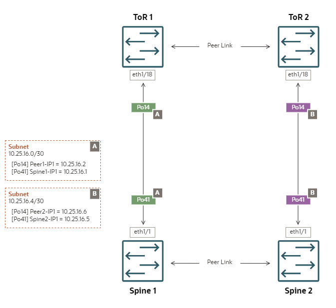
ECMP Square enables Layer 3 network deployment according to industry-proven best practices. This uplink topology is highly recommended.
Configuration Properties
-
Square topology – each spine switch is connected to a different independent data center switch
-
Static routing – all egress traffic from an uplink goes through a single gateway IP configured on its peer network device in the data center
-
ECMP – bandwidth optimization across multiple redundant links or paths
-
Separate /30 subnets – each uplink connects one spine switch port channel to one data center switch port channel in a /30 subnet
Topology Highlights
-
All uplinks are configured as LACP/active port channels with rate=fast
-
ToR switch ports connecting to the spine switches must be set up in access mode. Spanning tree protocol must be disabled. The ToR switches must NOT be configured with vPC.
-
Requires 2 unique subnets: a /30 subnet size is recommended, but /31 is possible if the ToR switches support it.
-
Equal cost static routes to both ToR switches are set up automatically.
-
Egress traffic can hash to any of the 2 uplinks.
-
It is NOT possible to isolate specific VCN/VM egress traffic through one particular uplink.
-

Detailed Spine Switch Configuration Example
-
Spine Switch 1
interface port-channel41
  description "customer uplink"
  no switchport
  mtu 9216
  speed 10000
  no negotiate auto
  ip access-group ingress-ports-acl in
  no ip redirects
  ip address 10.25.16.1/30
  ip nat outside
Routes added:
0.0.0.0/0, ubest/mbest: 2/0 *via 10.25.16.2, [20/0], 6d08h, static *via 10.25.16.6, [100/0], 6d08h, static -
Spine Switch 2
interface port-channel41
  description "customer uplink"
  no switchport
  mtu 9216
  speed 10000
  no negotiate auto
  ip access-group ingress-ports-acl in
  no ip redirects
  ip address 10.25.16.5/30
  ip nat outside
Routes added:
0.0.0.0/0, ubest/mbest: 2/0
  *via 10.25.16.6, [20/0], 6d07h, static
  *via 10.25.16.2, [100/0], 6d07h, static
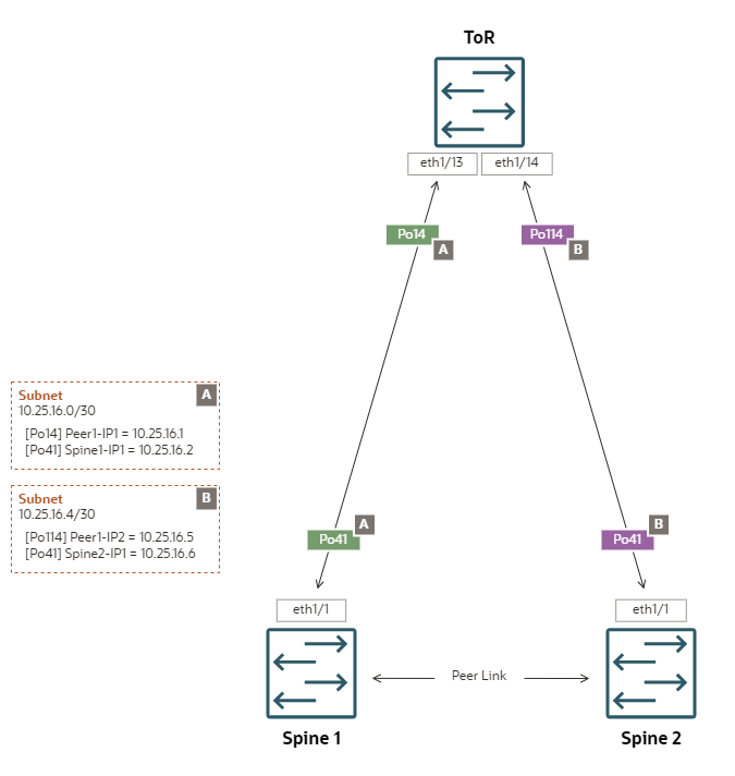
ECMP Triangle enables peering with a single data center router or switch.
Configuration Properties
-
Triangle topology – both spine switches are connected to a single data center switch
-
Static routing – all egress traffic from an uplink goes through a single gateway IP configured on its peer network device in the data center
-
ECMP – bandwidth optimization across multiple redundant links or paths
-
Separate /30 subnets – each uplink connects one spine switch port channel to one data center switch port channel in a /30 subnet
Topology Highlights
-
All uplinks are configured as LACP/active port channels with rate=fast
-
Port channel Po41 represents the set of links configured on both spine switches. Port channels Po14 and Po114 represent the corresponding sets of links configured on the ToR switch.
-
ToR switch ports connecting to the spine switches must be set up in access mode. Spanning tree protocol must be disabled.
-
Requires 2 unique subnets: a /30 subnet size is recommended, but /31 is possible if the ToR switch supports it.
-
Equal cost static routes to the ToR switch are set up automatically.
-
Egress traffic can hash to any of the 2 uplinks.
-
It is NOT possible to isolate specific VCN/VM egress traffic through one particular uplink.
-

Detailed Spine Switch Configuration Example
-
Spine Switch 1
interface port-channel41 no shutdown mtu 9216 ip address 10.25.16.2/30 no ipv6 redirects ip proxy-arp ip nat outside ip route 0.0.0.0/0 po41 10.25.16.1 20 ip route 0.0.0.0/0 po41 10.25.16.5 100 -
Spine Switch 2
interface port-channel41
  no shutdown
  mtu 9216
  ip address 10.25.16.6/30
  no ipv6 redirects
  ip proxy-arp
  ip nat outside

ip route 0.0.0.0/0 po41 10.25.16.5 20
ip route 0.0.0.0/0 po41 10.25.16.1 100
Topology for Segregated Administration Traffic
If you decide to segregate Compute Cloud@Customer administration traffic, you can cable and configure the dedicated connections for the administration network using the same topologies as the data network. All the same principles apply.
The administration network topology does not need to match the data network: it can be based on another reference topology, using a different number of physical ports operating at a different link speed. The uplink configuration does require different subnets, IP addresses and port channels, but otherwise looks exactly like a data network.
On the spine switches, the administration network is hard-coded to use port channel 45 (Po45), whereas the data network uses Po41 and Po42. On the data center side of the uplinks you are allowed to use any valid port channel ID that fits the existing data center configuration.